TDUK.2 System.
Back in the early 1960's the network usually comprised two squad cables plus one or two quad cables. One of the squads was used to relay the two television programmes, BBC.1 and ITA, and the remaining cables were used to distribute the sound-only programmes. The BBC.1 signal was transmitted on a 4·95 MHz carrier on one pair of the squad, and ITA on an 8·45MHz carrier on the other pair. The electrical information or signal required to produce a good quality 405-line picture spread out over a band of approximately 2·7 MHz to 3·0 MHz width and the range of frequencies encountered on the network was as shown in Figure 1.
Whenever two pairs of a cable were close together for any distance it was inevitable that a small amount of the signal on one pair was transferred on to the other pair and this produced crossview. The amount of signal that could be transferred from one pair to the other without the crossview being visible on the picture was about 28dB, or l/25.
lf a subscriber had an input of say 25mV on BBC.1 then the permissible amount of ITA that could appear on that pair was 1mV or less.
To enable the signals to pass over long lengths of cable and yet maintain satisfactory crossview protection, both V.T.R. and feeder repeaters were fitted with crossview traps. This was possible because, as shown in Figure 1, the alternative channel frequency was outside the range of those frequencies required to produce the wanted picture.
In other words, the amplifiers were designed to amplify the full range of frequencies of the wanted signal and to attenuate or reject the unwanted carrier. In this way any crossview on the incoming signal was removed and the ongoing signal was crossview free. In addition to this, wired receivers had a 3·5 Mhz crossview trap in the video stage, 3·5 Mhz being the difference between the two carriers.
This was acceptable because, after the signal was detected within the receiver, the upper frequency limit of the wanted signal was 2.75 to 3·0 Mhz as stated earlier, and any traps tuned to frequencies above this limit did not affect the picture quality.
The system was very good; so good that in terms of crossview only the most severe of faults gave rise to it.
5·4MHz and 8·3MHz Operation
In preparation for BBC.2 it was necessary to change the System Frequencies from 4·95 Mhz and 8·45 MHz to 5·4 MHz and
8·3MHz respectively.
Although the change in frequencies was relatively small, the difference between the carriers was reduced from the original spacing of 3·5 MHz to 2·9 Mhz. The new ranges of frequencies that were applied to the network are shown in Figure 2 and it will be seen that, because the carriers were closer together, the unwanted carrier was closer to the picture information frequencies of the wanted signal. Although it was possible to retune the crossview traps in the V.T.R. type of repeater (A.25D) to the new frequencies it was necessary in the feeder type of repeater (A.256) to remove the traps. because otherwise picture quality would have been affected.
This resulted in the disappearance of one of the methods of reducing crossview on the feeder. After the change in frequencies, new wired receivers were produced with 2·9 MHz crossview traps instead of the previous 3·5 MHz traps.
TD.20
Then came the day when BBC.2 was added to the network. BBC.2 transmissions were different in many ways from the existing signals: for instance the picture was made up of 625 lines instead of 405 lines. There were many other differences but the one which affected crossview was the increase in bandwidth.
As stated earlier, the bandwidth or range of frequencies required to produce a good quaIity 405-line picture was approaching
3·0 MHz, on 625-lines it was necessary to have a bandwidth of 5·5 MHz and all the equipment on the network had to be capable of passing this range of frequencies without introducing distortion.
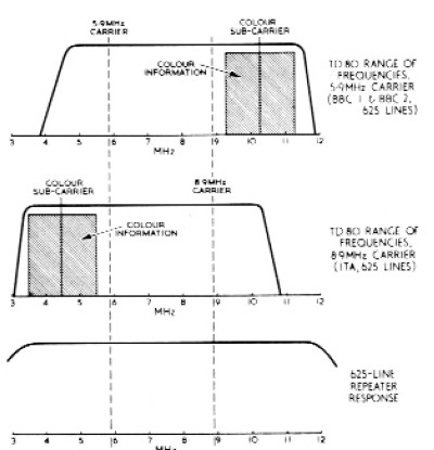
Figure 3 shows the 625 line transmission with its associated sidebands and it will be noticed that the range of frequencies extended beyond the 8·3 MHz carrier of the ITA signal. Both BBC.1 and ITA could interfere or cause crossview on the new|y·born BBC.2 signal.
Because BBC1 and BBC.2 carriers were synchronized, i.e. they were using the same carrier frequency, the protection required to prevent crossview being visible leapt from the previous 28dB to 45dB, or 1/170. In addition, because the two carriers were synchronized, crossview traps could not be used; a trap tuned to the unwanted carrier would also reject the wanted signal. As the two carriers were of the same frequency, the 2·9MHz crossview trap within the receiver did not offer any additional protection.
Normally BBC.2 was relayed in the second squad cable and consequently the amount of signal transferred from one squad cable on to the adjacent squad was considerably less than that transferred between two pairs of a squad cable. Nevertheless, at junction boxes, kiosks etc., the individual pairs.\ with the outer screen of the cable stripped back, were exposed; long untwisted pairs would give rise to crossview.
Until the introduction of BBC2, BBC.1 feeder repeaters normally operated with output levels in the region of 14 to 20V. With the greater band-width of BBC.2, however, it was necessary to restrict the output level to 10v (on 5·4 MHz) and in order to prevent crossview, BBC.1 (and ITA) levels were reduced similarly.
The ITA on 8·3 MHz could also produce crossview on the BBC2 signal and here the protection required was of the order of 31dB, or 1/36.
BBC.2 repeaters, both V.T.R. and feeder versions, could not be fitted with crossview traps because such traps, designed to reject 8·3 Mhz would have also removed some of the BBC2 signal information and could have affected the colour quality.
For the same reason, the 2·9 MHz trap within the wired receiver, when switched to 625-line operation, had to be damped to reduce its effectiveness; otherwise distortion would have occurred when viewing the 625-line programme.
TD.80
Carrier frequencies were changed to 5·9 MHz and 8·9 MHz so that several 625 line programmes could be distributed on the network.
By the early 1970's most networks were distributing at least BBC.1, BBC.2 and 1TA on 625-lines in colour and the problems associated with BBC.2 now equally apply to the other channels. The operating conditions are shown in Figure 4. The crossview protection requirements of network, compared with the TDUK.2 days, were as follows:-
(i) The original 2BdB crossview protection hab been increased to approximately 31 dB (measured at 8·9 MHz; 33dB measured at
5·9MH:) between a 5·9MHz and an 8·9 MHz carrier, and 45dB between carriers of the same frequency.
(ii) Crossview traps had now been removed from both V.T.R. and feeder repeaters.
(iii} The wired receiver crossview trap was less effective when the receiver was switched to 625-lines and on more modern
receivers the trap was omitted completely.
These facts alone emphasized the need for higher wiring standards as compared with the earlier requirements.
Cables
The period during which all the foregoing was happening also saw the introduction of multipair cables whereby up to six vision programmes could be distributed in the one cable. However, the same crossview protection requirements still applied and with multipair networks it was absolutely essential that the meaning of the terms "adjacents", "opposites" and "alternates", as shown in Figure 5, were fuliy understood including their implications.
To achieve the 45dB protection required between synchronized carriers it was absolutely essential that only alternate pairs were used for them, otherwise the required protection could not be achieved.
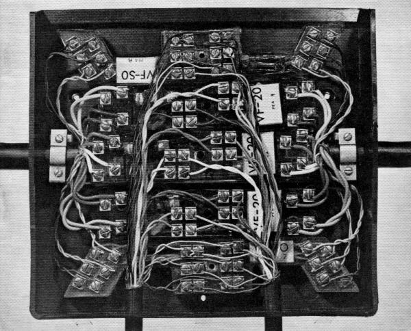
Untidy boxes, long untwisted pairs, etc., would all contribute to the crossview problem. The fact that in the feeder wiring to any one subscriber, there must be many junction boxes meant that the work involved in clearing crossview faults attributed to untidy boxes could be tedious and expensive.
The progression from TDUK.2 to the TD.80 system has so far been described in terms of crossview; two other factors, mismatches and h.f. interference, were also affected by the standard of wiring, will now be discussed.
Reflections
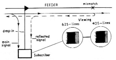
If a mismatch occured on the network, a portion of the signal was reflected back along it. A subscriber connected in front of such a mismatch, as shown in Figure 6, would see a reflection on the receiver as a secondary image displaced to the right of the main image. The distance between the wanted image and the unwanted image would depend on the length of cable between the sub-
scriber and the mismatch, and the speed of travel of the spot producing the picture on the c.r.t. of the television receiver.
0n 405 lines the spot would take approximately100us to scan one line of information, whilst with the receiver switched to 625-line operation it took only about 64us to complete one line. In other words the spot travelled about 1-1/2 times fasterwhen the receiver was switched to 625-lines than when it was switched to 405-lines.
Therefore if we imagine any echo as it will be seen on a subscribers receiver, the echo would appear 1-1/2 times further away from the main image when viewing on 625-lines than it would on 405 lines.
It is known that, for a given strength of echo, the further away it is from the image the more objectionable it would be. It was possible therefore that an echo which was just acceptable on 405-lines would be objectionable when viewing on 625-lines.
All inserts connected across the network produced a mismatch but when they were wired correctly, the magnitude of the mismatch was so small that the reflections were not visible. However, unless such proper precautions as the fitting of matching inserts and ensuring that spur inserts designed to feed two spurs actually fed two spurs and so on were taken, objectionable reflections would not be seen.
H.F. Interference
H.F. interference or patterning was a function of the levels on the network and the amount of interfering signals picked up by the network, the latter being dependent upon the degree of balance of the wiring.
As mentioned earlier, feeder output levels had been reduced: at the same time the transmitters producing the interfering signals had increased both in number and power.
The ratio between the wanted signal and unwanted signal had therefore been reduced and to counteract this it was necessary to improve the balance of the networks. This again could be achieved by tidy boxes and short, twisted tails.
Whilst the requirements of the network had increased, many new techniques had been introduced and network items which were superior to those they replaced.
Demonstration
To demonstrate that crossview could be introduced by untidy wiring, equipment was set up as shown in Figure 7. The output level of the signal generator was slowly increased until patterning was just visible on the receiver connected to the red pair. It could be seen that the patterning visible on the other receiver was very much worse and certainly not acceptable.
H.F. patterning susceptibility could also be demonstrated by connecting the output of the signal generator to a loop aerial and holding the aerial over one of the joints. Again the level of patterning on the receiver connected to the red pair would be very much weaker than that on the other receiver.

REDIFFUSION ENGINEERING LIMITED
Carlton House, Lower Regent Street
LONDON SW1Y 4LS
Associated Companies in over 175 towns in Great Britain and in Barbados, Bermuda. Canada, Ceylon, Guyana,
Hong Kong, Jamaica, Malaya, Malta, Singapore, South Africa, Trinidad and West Africa etc.
© rediffusion.info 2010
A look back at the Rediffusion Wired Vision System and the transition from 405 line to 625 line distribution
 |
Rediffusion JB122 |
|
 |
Figure 1. |
|
 |
Figure 2. |
|
 |
Figure 3. |
|
 |
Figure 6. |
|
 |
Figure 7. |
|
 |
Figure 4. |
|
 |
Figure 5. |
|


